

Differential
fuel flow meter
 Buy Online
 Compatible telematics units
 Image gallery
 Document Center
 Installation portfolio
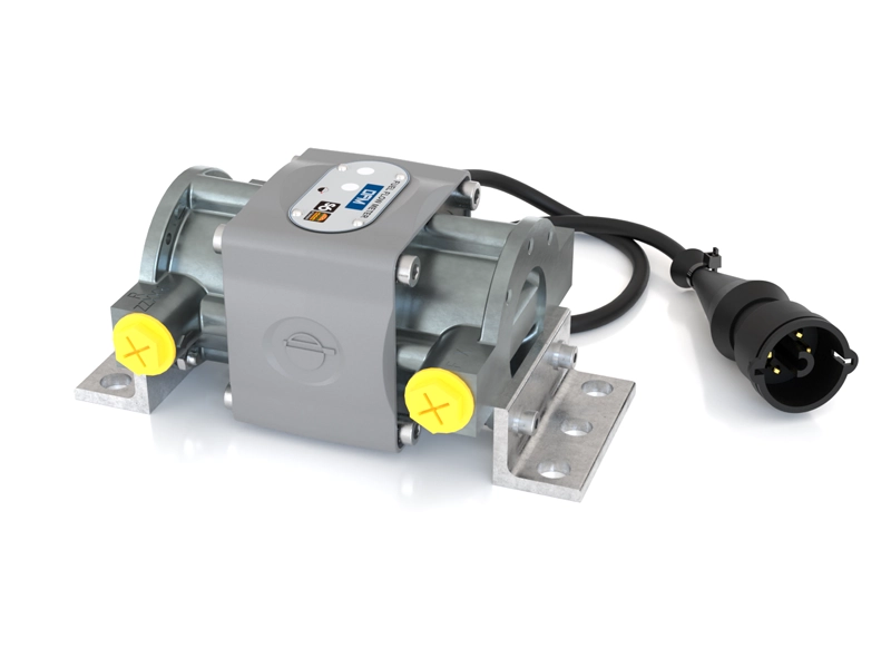
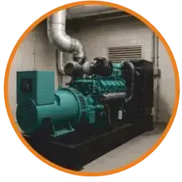
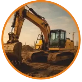
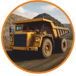
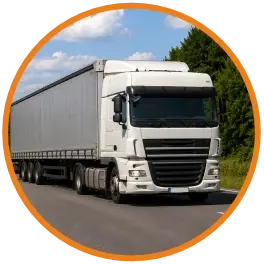
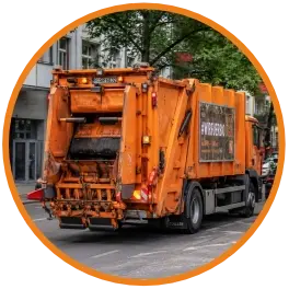
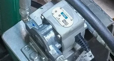
DFM D measures actual fuel consumption, operating time, and engine load modes for vehicles, diesel generators, and various industrial fuel consumers.
The key advantage of DFM D for fuel monitoring is direct measurement of fuel flow in the fuel lines. This ensures accurate measurements even during short operating cycles and when machinery is working on slopes.
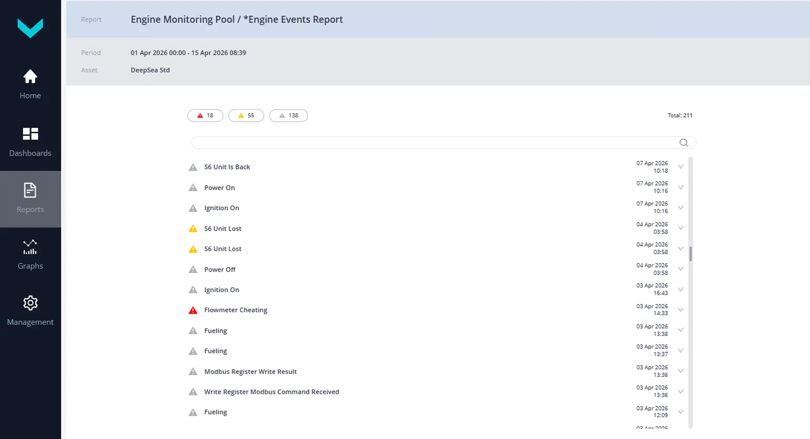
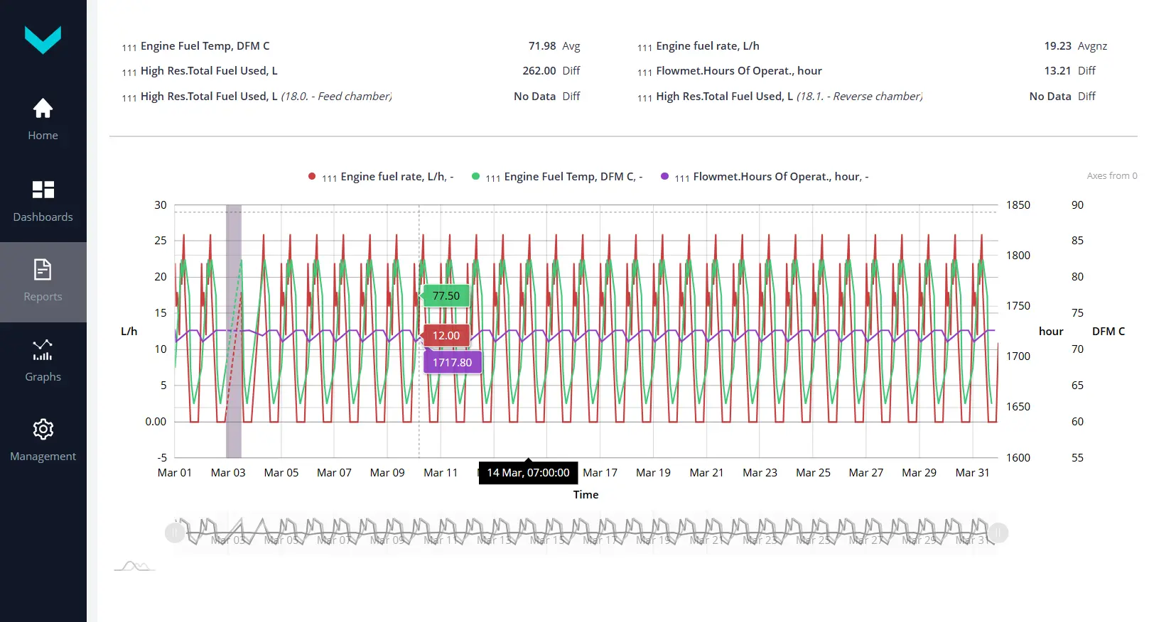
Data from the DFM D fuel flow meter helps automate the monitoring of actual fuel consumption and equipment operating time, detect inefficient fuel use and fuel consumption manipulation, and remotely identify faults and abnormal operation of the fuel system.
per chamber
per chamber
fuel consumption, operating time, temperature
How a differential fuel flow meter works
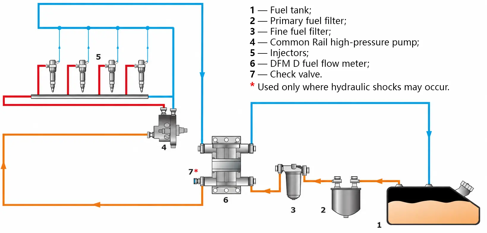
The diesel flow meter is installed in the fuel supply and return lines, which is essential for Common Rail fuel systems, unit injector systems, and other systems with a high volume of return fuel.
DFM D consists of two measuring chambers and an electronic module. The supply chamber measures fuel flow in the supply line, while the return chamber measures fuel flow returning to the tank. The electronic module calculates the difference and records fuel consumption, operating time, and operating modes.
The DFM D electronic module also stores accumulated data and generates an output signal (digital or pulse) for transmitting data to a vehicle telematics system or an industrial automation system.



Advantages of DFM D differential fuel flow meters
High accuracy on slopes and uneven terrain
DFM D readings remain stable in all operating positions of the equipment, unlike fuel consumption estimates based on changes in fuel level in the tank.
Accurate measurement during short operating cycles
During a short operating cycle, the fuel level in the tank changes very little. Measuring fuel flow directly in the fuel line makes it possible to determine consumption for each individual operation.
Accurate measurement in fuel systems with a return line
Two measuring chambers calculate net fuel consumption as the difference between supply and return flow — ideal for Common Rail and unit injector systems.
Metrological accuracy
Each flow meter is calibrated on a certified test bench, with a measurement error of no more than 1 % per chamber.
Measurement independent of external power supply
If the cable is disconnected or the vehicle power supply fails, measurement continues. The readings are stored and transmitted once power is restored.
Fuel meter tamper detection
Tampering attempts, such as blowing air through the chamber, are logged in dedicated counters and can trigger an alert.
Compatible with monitoring systems
Wired interfaces and the S7 wireless channel enable data transmission to telematics units, while a display can be used for standalone monitoring.
Fuel consumption and operating time counters
Fuel consumption
- Hourly fuel consumption, L/h
- Hourly fuel consumption in Supply chamber
- Hourly fuel consumption in Return chamber
- Total fuel consumption, L
- Total fuel consumption in Idling mode
- Total fuel consumption in Optimal mode
- Total fuel consumption in Overload mode
- Total fuel consumption in Negative mode
Engine operating time
- Total operating time, h
- Operating time in Idling mode
- Operating time in Optimal mode
- Operating time in Overload mode
- Operating time in Negative mode
- Operating time of Supply chamber
- Operating time of Return chamber
- Chamber operating time in all fuel consumption modes
Special parameters
- Operating time in Tampering mode, h
- Operating time in Interference mode, h
- Fuel consumption in Tampering mode, L
- Current engine mode by fuel consumption
- Fuel temperature
- Total CO₂ emissions
- Hourly CO₂ emissions
More than 30 counters and parameters are available via the output interface. See the operating documentation for details.
Fuel consumption monitoring in GPS tracking systems
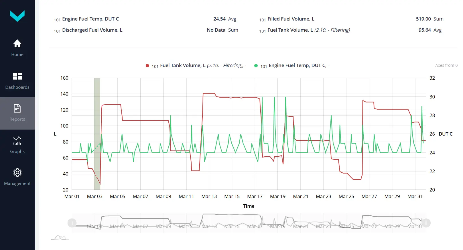
DFM D transmits data to an on-board telematics unit (GPS tracker), which sends it to cloud-based fleet management software.
DFM D is compatible with GPS trackers and telematics units from leading manufacturers. Ready-made instructions are available for fuel flow meter connection and telematics unit configuration.
Check compatibility with telematics unit →
Popular cloud platforms for vehicle tracking and fleet management are used to display the data. The largest data volume is available in the UNUM IIoT Platform.
Learn more about UNUM IIoT Platform →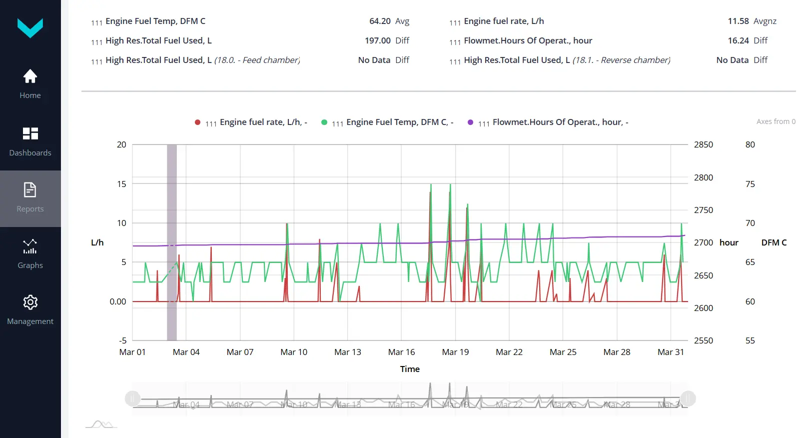
Types of DFM D differential fuel flow meters
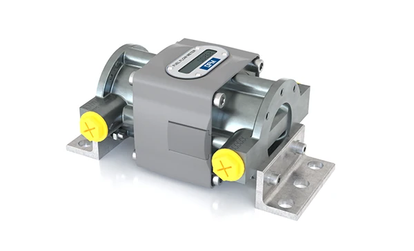
Stand-alone fuel counter
Fuel consumption meter for local accounting of fuel use and machinery operating time.
- Built-in LCD display
- Power supply from built-in battery
- No connection to online software
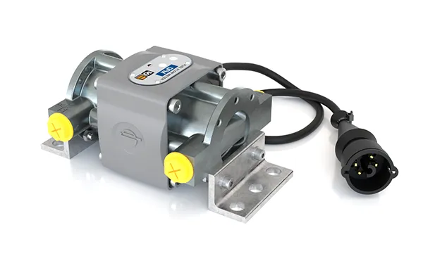
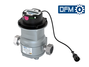
Fuel flow meter with cable
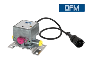
Wired interface for data transfer to a telematics unit.
- CAN j1939/S6, RS-232/485 Modbus, pulse output
- Integration into GPS tracking systems
- Maximum data on fuel consumption
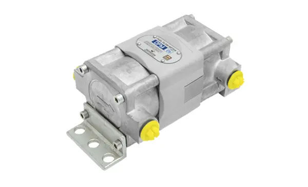
Wireless fuel flow meter
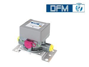
Wireless data transfer to telematics units and smartphones.
- Radio channel based on S7 Technology
- Data monitoring in online software and mobile app
- Convenient installation without cable routing
Differential fuel flow meter for heavy-duty
operating conditions
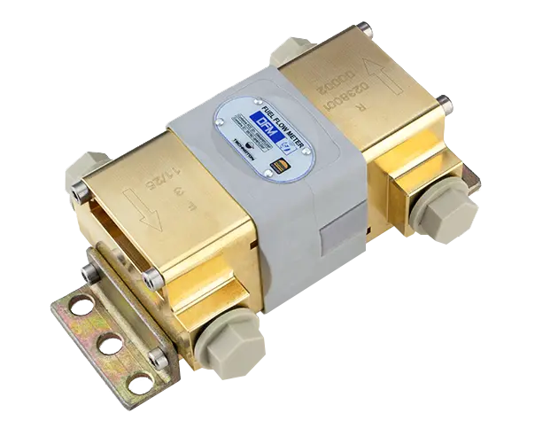
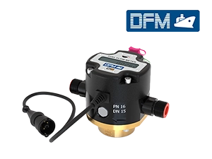
DFM 900D — the first fuel flow meter in the product line with throughput capacity up to 900 L/h in each measuring chamber. Designed for marine engines, powerful diesel generators and heavy mining machinery where standard models do not provide sufficient flow rate reserve.
The DFM 500HP D, a special-order version with up to 600 L/h per chamber, also has a brass body.
- Maximum flow rate in each measuring chamber — up to 900 L/h
- Connection thread G 1/2"
- Corrosion-resistant brass body
- Marine engines, diesel generators, heavy machinery
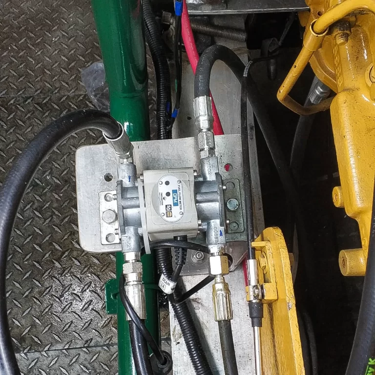
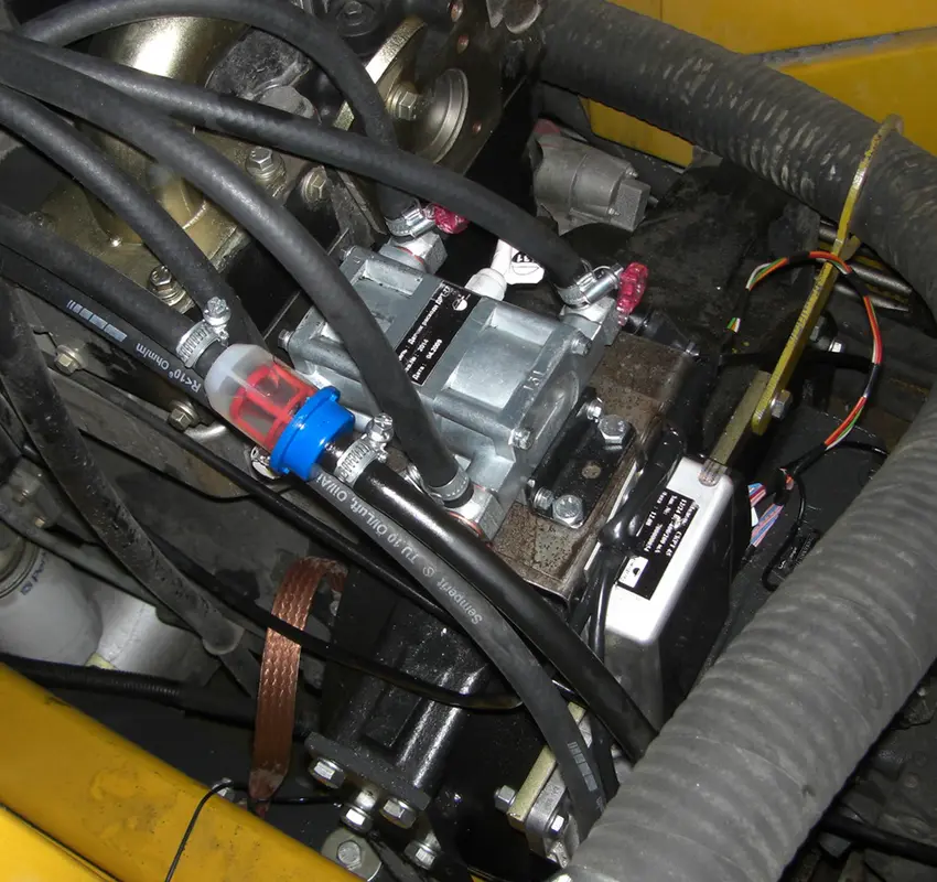
DFM D fuel flow meter installation into the fuel system
DFM D is installed in the fuel supply and return lines without altering the fuel system or engine configuration. Chamber “F” is installed in the supply line, while chamber “R” is installed in the return line. The standard installation is downstream of the low-pressure lift pump. Other installation options are also possible and are described in the operating manual.
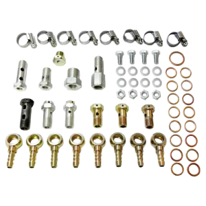
Installation takes 1–2 hours and is carried out by one trained fuel monitoring installer. We recommend the MK DFM mounting kit with fittings for the specific size. The installation process is described in detail in the operating manual and installation diagrams.
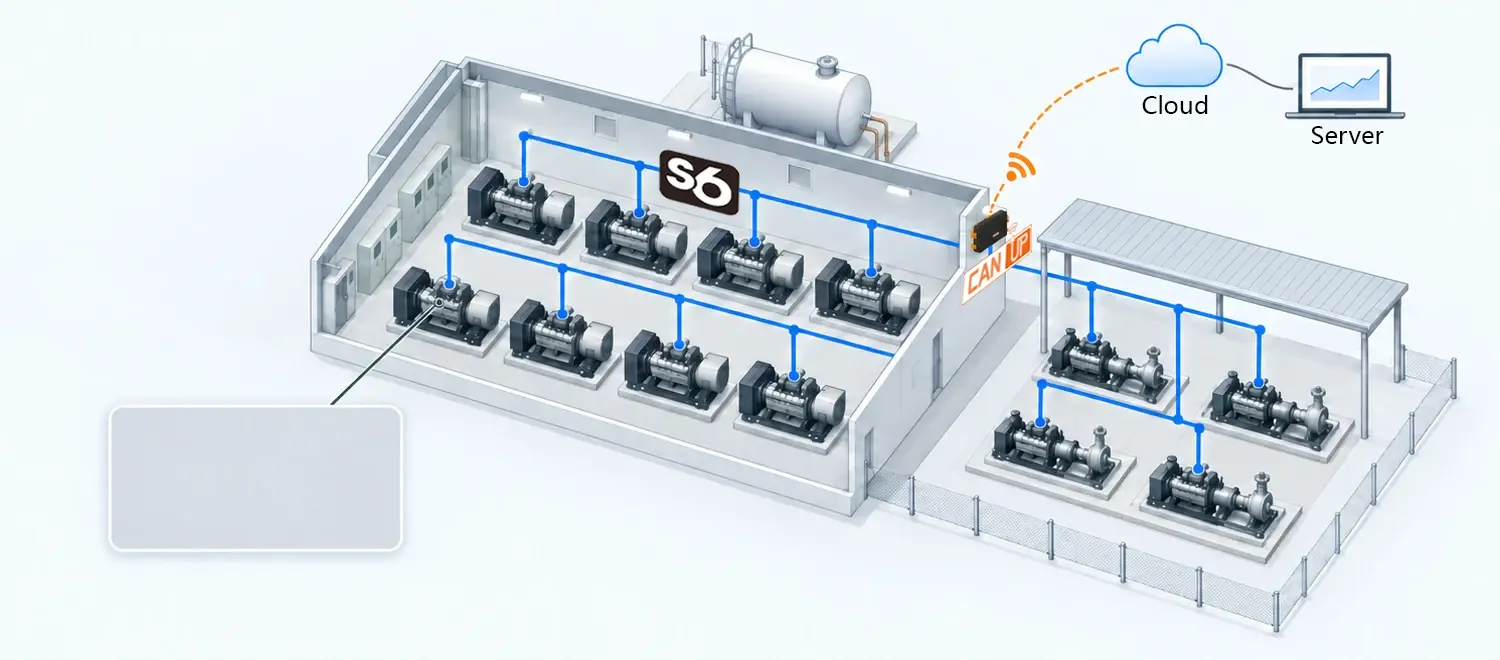
Fuel consumption monitoring for up to 32 consumers at a single site
S6 technology connects up to 32 DFM fuel flow meters into a single network using one common cable. All devices transmit data and can be configured and diagnosed via a shared CAN j1939/S6 bus.
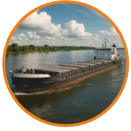
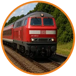
Such networks are used at sites with multiple fuel consumers, including vessels, locomotives, genset sites, and industrial facilities.
- The entire network connects to a single telematics unit or gateway
- Up to 32 fuel flow meters in one network
- Configuration and diagnostics of all devices from a single PC
- SAE J1939 protocol
Accessories for DFM fuel flow meter installation
Technical specifications
| Connection thread | M14×1.5 / M16×1.5 / G 1/2" |
| Nominal pressure | 2 bar |
| Maximum pressure | 25 bar |
| Power supply voltage range | 10…45 V |
| Current consumption at 12 V / 24 V | 50 / 25 mA |
| Maximum fluid temperature | +85 °C |
| Operating temperature range, without / with display | −40…+85 / −20…+60 °C |
| Ingress protection rating | IP54 (IP67 — on request) |
| Measurement error (per chamber) | no more than 1% |
| Differential measurement error | 1–3%, depending on the ratio of fuel flow rates in the supply and return lines |
| Kinematic viscosity | 1.5…6.0 mm²/s |
| Model | Chamber volume, mL | Min. flow rate per chamber, L/h | Max. flow rate per chamber, L/h |
|---|---|---|---|
| DFM 100D* | 5 | 10 | 100 |
| DFM 250D* | 12.5 | 50 | 250 |
| DFM 500D* | 20 | 100 | 500 |
| DFM 900D | 20 | 100 | 900 |
* On special order, HP versions are available with an increased maximum flow rate in each measuring chamber: DFM 100HP D up to 120 L/h, DFM 250HP D up to 300 L/h, and DFM 500HP D up to 600 L/h. Like the DFM 900D, the DFM 500HP D features a corrosion-resistant brass body designed for marine applications and harsh operating conditions.
Which model to choose?
Determine the maximum engine fuel flow rate
The model is selected by the fuel flow rate in the supply line. It is higher than the engine's rated consumption because part of the fuel goes to the return line.
Select connection type
Stand-alone with display, wired (pulse, RS-232, RS-485, CAN j1939/S6) or wireless (BLE/S7). The choice depends on the telematics unit.
Consider operating conditions
For water transport and corrosive environments, choose the brass-body models DFM 500HP D and DFM 900D. For standard applications: DFM 100D, 250D, 500D.
We will help you select the right model
Tell us about your task — we will select the appropriate model and installation diagram.
Send requestDocuments and certificates
- Type approval certificates for measuring instruments
- Approvals from classification societies
- Certificates and declarations of conformity
- Explosion protection certificates
- Accuracy verification procedures and metrological certification
- OEM installation approval records
- Operating manuals
Other products for fuel and oil consumption monitoring
Fuel flow meter selection
Contact us and Technoton specialists will help you select a fuel flow meter for your application.