![]()
DFM Marine
flow meter for heavy machinery


DFM Marine is used in telematics systems (GPS tracking systems) and as an autonomous fuel monitoring solution. DFM Marine is installed in fuel line of the engine / boiler / burner, directly measures fuel consumption and generates an output signal, which is sent to telematics unit (GPS tracker).
DFM Marine is used for monitoring fuel consumption and operating time of engine (fuel consumer), and suitable for:
- water transport – sea and river vessels;
- locomotives and railway machines;
- quarrying and mining machinery;
- powerful diesel generators, boilers, burners.
Tasks
Advantages of DFM Marine
Measuring chamber made of brass
Measuring chamber is made of corrosion-proof and highly durable material – brass.
Different material and fuel line connection type designs
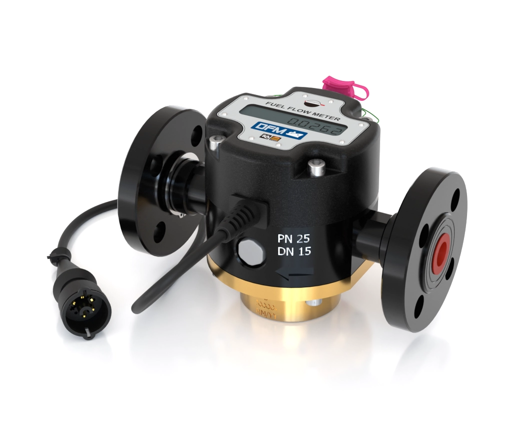
Body and fuel line connections of DFM Marine can be made of duralumin (lighweight and inexpensive) or brass (corrosion-proof and more durable). Fuel line connection types – thread or flange – specified in purchase order.
Operation in differential fuel consumption measurement mode
Any two units of DFM Marine are configured from PC to operate in paired mode, without a need of selecting and calibrating two compatible pieces. Differential fuel consumption measurement mode is used for measuring consumption of fuel in supply and return fuel lines of an engine, if necessary.
Fuel consumption and operating time Counters
Fuel consumption
- Instant fuel consumption, m3/h
- Total fuel consumption, m3
- Total fuel consumption in “Idling” mode of engine operation
- Total fuel consumption in “Optimal” mode of engine operation
- Total fuel consumption in “Overload” mode of engine operation
- Resettable fuel consumption counter
- Total CO2 Emission
- Hourly CO2 Emission
Engine operating time
- Total operating time, h
- Total operating time in “Idling” engine operation mode
- Total operating time in “Optimal” engine operation mode
- Total operating time in “Overload” engine operation mode
- Resettable operating time Counter
Special
- Engine operating time in “Tampering” mode, h
- Engine operating time in “Interference” mode, h
- Current engine operation mode as per fuel consumption rate
- Fuel temperature
- Temperature correction status
- Correction coefficient value
- Event alarms: “Power on/off”, “Tampering”, “Interference, etc.
- Battery charge
DFM Marine models
The DFM Marine product line includes the following models:

*Interfaces: RS-232 (protocol DFM COM (LLS) and RS-485 (protocol Modbus) on request
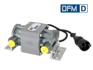
 With display only (autonomous fuel flow meter)
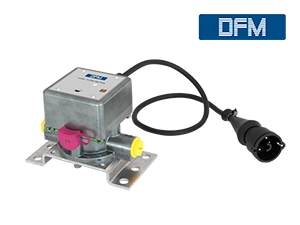
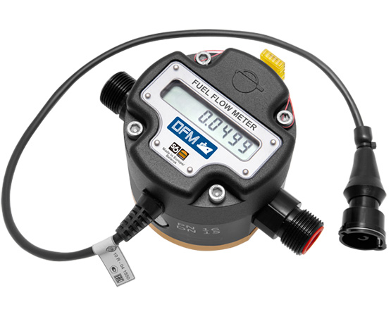 Output signal cable + display
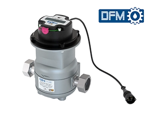
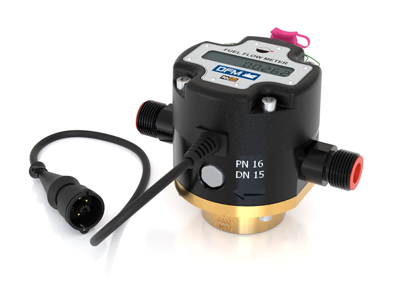
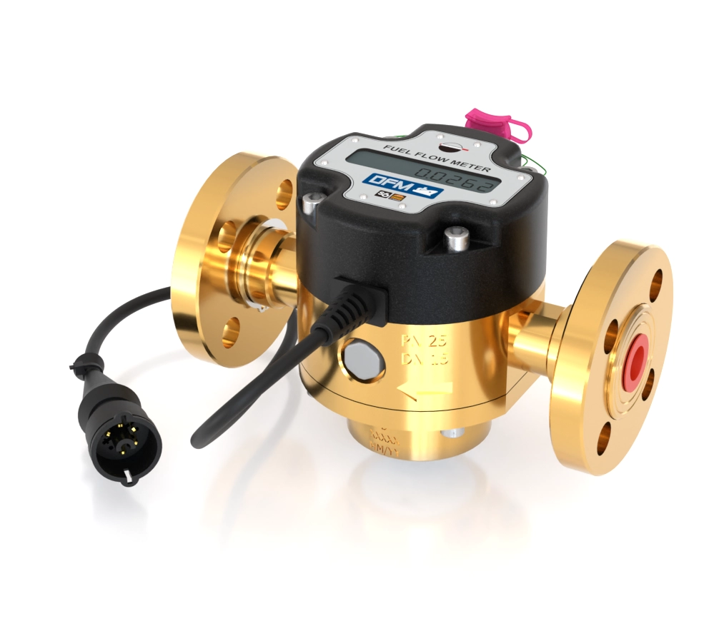
DFM Marine design
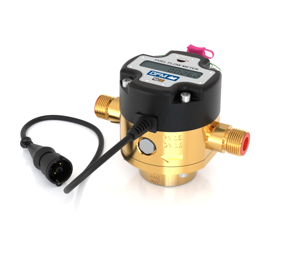
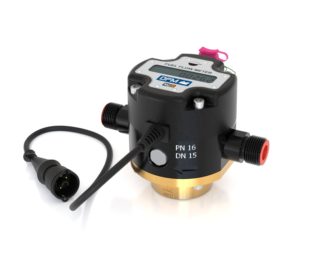
Brass body
Thread connections
Brass body
Flange connections
Duralumin body
Thread connections
Duralumin body
Flange connections
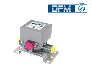
Wireless Fuel Flow Meters DFM Marine S7

DFM Marine S7 – wireless fuel flow meter engineered for marine vessels, heavy-duty machinery, and stationary engines
Connect in minutes — no cables required. Powered by a long-life built-in battery. Sends real-time fuel data via Bluetooth Low Energy straight to telematics device, muiltuple displays and mobile app.
Seamlessly integrates with NMEA2000 to display fuel consumption directly on your onboard screen.
Discover more
Flow range: 20–4000 L/h
Durable brass chamber
Interfaces: BLE / CAN / Pulse
🔋 5 Years of Autonomous Operation
Built-in battery eliminates the need for external power and reduces installation time — especially where cable routing is difficult.
Bluetooth Low Energy
Wireless data transfer to a smartphone or onboard terminal. Monitor fuel consumption and engine hours in the dedicated mobile app.
📱 Mobile App
Instant and total fuel consumption, engine mode tracking, event logging, and tamper alerts — all on your smartphone screen.
⚙️ Professional Metrics
Mode-based reporting: idle, optimal, overload. Shift analysis and recommendations for the most fuel-efficient operation.
🛡 Anti-Tampering Protection
Detects manipulations and fuel fraud. All incidents are logged for audit and service diagnostics.
🚢 Marine & Industrial Applications
Brass measuring chamber, duralumin/brass housing, swivel flange, and vent valve — built for reliability in vessels, locomotives, and gensets.
DFM Marine installation and connection
DFM Marine fuel flow meter is installed in fuel line after fine filter:
- per “pressure side” scheme, after low-pressure pump
- per “suction side” scheme, before low-pressure pump
For more information about the installation process, including installation schemes description, refer to DFM Marine Operational Manual in Document Center.
You can also order training on installation and configuration of DFM Marine.

Accessories for installation of DFM Marine


Diagnostics and configuration of DFM Marine

DFM Marine diagnostics function allows to evaluate performance of the flowmeter and applicability of DFM Marine settings to fuel system operation parameters. In “Diagnostics” menu, a chart of instant fuel consumption is available, as well as fuel temperature in the chamber, self-diagnostics codes of flow meter, Journal of logged Events – “Power on/off”, switching to “Tampering” and “Interference” operation modes.
DFM Marine is configured with Service S6 DFM software available for PC. It is possible to adjust the following settings of DFM Marine:
- Boundaries of operation modes – “Idling”, “Optimal”, “Overload”, “Tampering”, “Interference;
- correction and temperature correction coefficient
- units of measurement (Metric/US)
Maximum pressure:
flange connection
thread connection
25 atm
16 atm
Maximum temperature of working fluid
95°С
150°С*
Fluid viscosity
1,5 – 6,0 mm2/s (cSt)
Measurement chamber material
brass
Body/connection materials
brass/duralumin**
Inaccuracy rate
see tab “Measurement range and accuracy”
Communications standard
CAN J1939/S6 + NMEA2000 digital interface
RS232/485 (protocols: Modbus and DFM COM (extended LLS)) interfaces
pulse output
Ingress Protection Rating
* – аvailable on request
** – specified in the order
IP 54 (IP67*)
Measurement range and accuracy of DFM Marine flow meters
| Model (by size) | Starting flow rate*, m³/h | Minimum flow rate (Qmin), m³/h | Maximum flow rate (Qmax), m³/h | Relative accuracy error, %, not more than*** |
| DFM Marine 1000 | 0,01 | 0,02 | 1 | ±0,5** |
| DFM Marine 2000 | 0,02 | 0,04 | 2 | |
| DFM Marine 4000 | 0,04 | 0,08 | 4 | |
| * Minimum threshold flow rate value when the meter starts operating. ** In differential/summarization measurement mode, inaccuracy is not higher than ±1.0 % ***If fuel consumption in the range from Qmin to 3∙Qmin, the allowed inaccuracy is not more than ±1.0 %,
| ||||
DFM Marine power supply modes:
- Stand-alone power supply (DFM Marine C models) DFM Marine is powered from the built-in lithium-silicon battery. Estimated DFM Marine operation time until full battery discharge is not less than 36 months.
- Combined power supply (DFM Marine CK/CCAN models) — DFM Marine is powered from the external power source or built-in battery (in case external power is off). Power supply is switched to stand-alone mode in case of low level of external power supply (less than 8 V). Estimated DFM Marine operation time in this mode is not less than 36 months.
Specifications
| Maximum pressure with flange connection | 25 atm |
| Maximum pressure with flange connection | 16 atm |
| Maximum temperature of working fluid | 95°С, 150°С* |
| Fluid viscosity | 1,5 – 6,0 mm2/s (cSt) |
| Measurement chamber material | brass |
| Body/connection materials | brass/duralumin** |
| Inaccuracy rate | see tab “Measurement range and accuracy” |
| Communications standard | CAN J1939/S6 + NMEA2000 digital interface RS232/485 (protocols: Modbus and DFM COM (extended LLS)) interfaces pulse output |
| Ingress Protection Rating | IP 54 (IP67*) |
| * – аvailable on request | |
| ** – specified in the order | |
Power supply
DFM Marine power supply modes:
- Stand-alone power supply (DFM Marine C models) DFM Marine is powered from the built-in lithium-silicon battery. Estimated DFM Marine operation time until full battery discharge is not less than 36 months.
- Combined power supply (DFM Marine CK/CCAN models) — DFM Marine is powered from the external power source or built-in battery (in case external power is off). Power supply is switched to stand-alone mode in case of low level of external power supply (less than 8 V). Estimated DFM Marine operation time in this mode is not less than 36 months.
Video